Difference between revisions of "An Advanced Terrain and Megatexture"
| (34 intermediate revisions by 3 users not shown) | |||
| Line 1: | Line 1: | ||
| − | This guide will show you step by step, on how to create a detailed Megatextured Terrain. | + | [[Image:AdvMega_Intro.jpg|thumb|500px|right]] |
| − | + | This guide will show you step by step, on how to create a detailed Megatextured Terrain. | |
| − | = Introduction = | + | '''Please ensure you are familiar with [[A Simple First Megatexture]] before attempting this tutorial.''' |
| + | |||
| + | == Introduction == | ||
'''For this tutorial you must:''' | '''For this tutorial you must:''' | ||
* Have a modelling package that can export as LWO, ASE or OBJ | * Have a modelling package that can export as LWO, ASE or OBJ | ||
* Have basic modelling skills | * Have basic modelling skills | ||
| − | * Have basic mapping skills, as in [[A Simple First | + | * Have basic mapping skills, as in [[A Simple First Terrain]] |
'''This tutorial covers:''' | '''This tutorial covers:''' | ||
| Line 26: | Line 28: | ||
* How to use Mudbox / ZBrush / World Machine / Blender / Lightwave / Maya / 3DSMax | * How to use Mudbox / ZBrush / World Machine / Blender / Lightwave / Maya / 3DSMax | ||
| − | '''If you already have a terrain mesh''', and do not want to use Mudbox and World Machine, skip to [[#Prepare Terrain for Megatexture|Prepare Terrain for Megatexture]] . | + | '''If you already have a terrain mesh''', and do not want to use Mudbox and World Machine, skip to [[#Prepare Terrain for Megatexture|Prepare Terrain for Megatexture]]. |
| − | = Mudbox: Shape the Terrain = | + | == Mudbox: Shape the Terrain == |
[[Image:AdvMega_Mudbox.jpg|thumb|128px|right|Mudbox Layers]] | [[Image:AdvMega_Mudbox.jpg|thumb|128px|right|Mudbox Layers]] | ||
These are the basic steps for sculpting a terrain in Mudbox. | These are the basic steps for sculpting a terrain in Mudbox. | ||
| Line 35: | Line 37: | ||
* Change any tools you use to have the edit ''Direction'' set to ''Y'' axis. | * Change any tools you use to have the edit ''Direction'' set to ''Y'' axis. | ||
* Create a new Layer, and sculpt the rough layout for the terrain. | * Create a new Layer, and sculpt the rough layout for the terrain. | ||
| − | * Subdivide again to | + | * Subdivide again to the level of detail you want (or can). |
* Create another layer, and sculpt more details into the terrain. | * Create another layer, and sculpt more details into the terrain. | ||
* Export to OBJ. | * Export to OBJ. | ||
| + | {{clear}} | ||
| + | == Convert Mesh to Heightmap == | ||
| + | This step is needed if you want to import your current terrain mesh into World Machine. | ||
| + | * Firstly, rotate the terrain mesh. In Lightwave, rotate -90° around the X axis. For 3ds Max & Maya, rotate +90° around the X axis. | ||
| + | * Cap any holes in the mesh, and triangulate the mesh. | ||
| + | * Using a machine with an nVidia graphics card, run the following command in the ETQW console to get the heightmap (where <model> is the relative path of the ''.lwo'', ''.obj'' or ''.ase'' mesh): | ||
| + | ** {{consolecmd|RenderBumpFlat –floatHeightmap -size 2048 2048 <model>}} | ||
| + | * An ''.r32'' (raw 32-bit) heightmap will be saved into the same folder as your model, this heightmap can be used in World Machine. | ||
| + | == World Machine: Adding Flow == | ||
| + | [[Image:AdvMega_WorldMachine.jpg|thumb|320px|right|World Machine Device View]] | ||
| + | [http://www.world-machine.com World Machine] is used to add erosion flow lines to the terrain. It's also useful as the flow maps can be exported to help create masks for texture distribution later in [[Terrain_Editor|Terrain Editor]]. These are the basic steps made to build the World Machine device nodes. | ||
| + | * Blend the heightmap made from the Mudbox mesh with ''Perlin Noise'' to help the ''Erosion'' filters. | ||
| + | * Use a ''Snow'' filter around the rocks (mask used), so rocks look like they are sitting in soil. | ||
| + | * Pass the heightmap through two ''Erosion'' nodes, which are set up differently, and combined give a natural flowing look. Both ''Erosion'' nodes are masked around the rocks, so they will keep their shape. The first ''Erosion'' node is setup as ''Channeled Erosion'' with an ''Inverse Filter'', carving large flow lines into the terrain. The Second is a ''Channeled Erosion'' set with ''No Filter'' , adding finer detailed flow lines. | ||
| + | {{clear}} | ||
| + | [[Image:AdvMega_WM_Output.jpg|thumb|150px|right|World Machine Heightmap]] | ||
| + | * The heightmap output of the erosion is split so the heightmap can be saved (and later used to create a mesh), and further filters created (sediment and normal map) to help make masks for texture distribution later. | ||
| − | |||
| − | |||
| − | |||
| − | |||
| − | |||
| − | |||
| − | |||
| − | |||
| − | |||
| − | |||
| − | |||
| − | |||
[[Image:AdvMega_WM_Flow.jpg|thumb|100px|right|Flow Map]] | [[Image:AdvMega_WM_Flow.jpg|thumb|100px|right|Flow Map]] | ||
| − | |||
| − | |||
| − | |||
| − | |||
| − | |||
* ''Flow'' and ''Deposition'' maps from the Erosion nodes are passed through ''Simple Transformation'' nodes that brighten the output saved. | * ''Flow'' and ''Deposition'' maps from the Erosion nodes are passed through ''Simple Transformation'' nodes that brighten the output saved. | ||
* The heightmap saved above is imported and rendered at a lower (usable) resolution to the ''Mesh Output'' node creating an OBJ mesh. | * The heightmap saved above is imported and rendered at a lower (usable) resolution to the ''Mesh Output'' node creating an OBJ mesh. | ||
| + | This World Machine example was given using World Machine 2, which is currently in [http://www.world-machine.com/blog/ Beta]. A couple of features show aren't available in World Machine v1.25. They are the ''Snow'' node (which isn't needed) and ''Mesh Output''. An alternative to creating a mesh from a heightmap [[Making_a_Terrain_Model#Optimising_to_Game_Mesh|can be found here]]. | ||
| + | {{clear}} | ||
| − | + | == High to Low poly == | |
| − | = High to Low poly = | + | === Optimizing === |
| − | [[Image:AdvMega Dags.jpg|thumb|320px|right| | + | [[Image:AdvMega Dags.jpg|thumb|320px|right|Dangling border polygons to delete]] |
| − | This stage will briefly explain how the high poly mesh exported from World Machine | + | This stage will briefly explain how the high-poly mesh exported from World Machine can be optimized down to the low poly game mesh. |
* Load the OBJ exported from [[#World Machine: Adding Flow|World Machine]] into your preferred 3d Application. | * Load the OBJ exported from [[#World Machine: Adding Flow|World Machine]] into your preferred 3d Application. | ||
* Rotate so it's orientated correctly. | * Rotate so it's orientated correctly. | ||
| − | * The outer mesh border will look like it's been dragged down (an artifact from the mesh being built from a heightmap). So remove this by selecting the mesh border polygons and delete. | + | * The outer mesh border will look like it's been dragged down (an artifact from the mesh being built from a heightmap). So remove this by selecting the mesh border polygons, and delete them. |
| − | * Triangulate and save out as OBJ, so it can be loaded into Lightwave. | + | * Triangulate the mesh and save out as ''.OBJ'', so it can be loaded into Lightwave. |
| − | * In Lightwave use a plug-in called [http://amber.rc.arizona.edu/lw/qemloss3.html qemLOSS3](once installed, found in the Utilities tab) to reduce the polygons to a reasonable amount ( | + | * In Lightwave, use a plug-in called [http://amber.rc.arizona.edu/lw/qemloss3.html qemLOSS3] (once installed, found in the Utilities tab) to reduce the polygons to a reasonable amount (ETQW used around 30,000 polygons for the 32,768 unit width terrain). If you have trouble running qemLOSS3, apply a different material other than the default. |
* Fix edges that are triangulated in the wrong direction. | * Fix edges that are triangulated in the wrong direction. | ||
| − | * Smooth subdivide the mesh, and run your mesh through qemLOSS3 again (to the same | + | * Smooth subdivide the mesh, and run your mesh through qemLOSS3 again (to the same polygon count as before). This will give a smoother terrain, easier for player movement and with less harsh silhouette angles. Repeat until you're happy with the mesh smoothness. |
| − | * Again fix edges that are triangulated in the wrong direction. | + | * Again fix edges that are triangulated in the wrong direction (these show up most obviously by applying a shiny material, and making sure the mesh has a single smoothing group (all soft edges, 180 degree smoothing angle). |
| − | * If you plan on having water, cut the mesh along the waterline | + | * If you plan on having water, cut the mesh along the waterline, so no polygons are both above or below the water. This is so the [[#Water Fog|water fog]] has a clear line to stop at. |
| − | + | {{clear}} | |
| − | |||
| + | === UV the Terrain === | ||
[[Image:AdvMega_UV.png|thumb|200px|right|UV Layout]] | [[Image:AdvMega_UV.png|thumb|200px|right|UV Layout]] | ||
| − | |||
This process is written for Maya, other 3d packages will have to modify the process. | This process is written for Maya, other 3d packages will have to modify the process. | ||
* To achieve relaxed UV borders use a mel script called worldSpaceUVLine - it can be found on [http://Highend3d.com/maya/downloads/mel_scripts/modeling/poly_tools/4508.html Highend3D]. Copy the .mel into your ''My Documents\maya\#.#\scripts'' folder and run by typing '''''worldSpaceUVLine;''''' in the Maya command line. | * To achieve relaxed UV borders use a mel script called worldSpaceUVLine - it can be found on [http://Highend3d.com/maya/downloads/mel_scripts/modeling/poly_tools/4508.html Highend3D]. Copy the .mel into your ''My Documents\maya\#.#\scripts'' folder and run by typing '''''worldSpaceUVLine;''''' in the Maya command line. | ||
* Snap all 4 corners to the UV 0-1 square. Select all the edge uv for one side, and in the worldSpaceUVLine tool select the corresponding UV layout direction (U for horizontal, V for vertical), and press the align UV’s on selected line button. Repeat for each side. | * Snap all 4 corners to the UV 0-1 square. Select all the edge uv for one side, and in the worldSpaceUVLine tool select the corresponding UV layout direction (U for horizontal, V for vertical), and press the align UV’s on selected line button. Repeat for each side. | ||
* Make sure all holes in the mesh are capped, and run the Relax UVs tool, with the option ''Edge Weights'' set to ''World Space'', and ''Pin UV Border'' selected. Keep repeating Relax UVs until you see no more UV movement. | * Make sure all holes in the mesh are capped, and run the Relax UVs tool, with the option ''Edge Weights'' set to ''World Space'', and ''Pin UV Border'' selected. Keep repeating Relax UVs until you see no more UV movement. | ||
| + | {{clear}} | ||
| − | + | === Perturbate Image (Normal Map) === | |
| − | |||
| − | |||
| − | |||
| − | |||
| − | |||
[[Image:AdvMega_Perturbate.jpg|thumb|200px|right|Perturbate Image (Tangent Space Local Map)]] | [[Image:AdvMega_Perturbate.jpg|thumb|200px|right|Perturbate Image (Tangent Space Local Map)]] | ||
| − | |||
The Perturbate Image is an image that is [[#Construct the Megatexture|applied to the megatexture]], and corrects the low poly mesh normal to match that of the high poly. | The Perturbate Image is an image that is [[#Construct the Megatexture|applied to the megatexture]], and corrects the low poly mesh normal to match that of the high poly. | ||
* Load the high and low poly mesh into your preferred 3d Application. | * Load the high and low poly mesh into your preferred 3d Application. | ||
| − | * | + | * Use a surface-sampler (also known as baking textures, or render-to-texture, most good 3D applications will have this capability) to render the high poly normals onto the low poly model, with normals set to "tangent space". |
| − | * You | + | * You probably will need to fix the normal map channels (red and green) as the 3D Application use normals maps differently to the Game. Make sure the green channel has white facing down, and red has white facing right. |
| + | {{clear}} | ||
| + | |||
=== Convert World Machine masks to UV space === | === Convert World Machine masks to UV space === | ||
| − | All the masks created created in World Machine (flow, deposition | + | [[Image:AdvMega_LowPoly.jpg|thumb|400px|right|Low Poly Mesh with Local Map]] |
| − | * Load the high and low poly mesh into your preferred | + | All the masks created created in World Machine (flow, deposition etc.) won't match the new game mesh UV coordinates |
| + | * Load the high and low poly mesh into your preferred 3D application. | ||
* Duplicate the game mesh and apply a planar UV projection. | * Duplicate the game mesh and apply a planar UV projection. | ||
* Apply the masks created in World Machine to the planar mapped mesh. | * Apply the masks created in World Machine to the planar mapped mesh. | ||
* Surface sample the diffuse from the planar mapped mesh, onto the game UV mesh. | * Surface sample the diffuse from the planar mapped mesh, onto the game UV mesh. | ||
Also render the mesh normals (world space) to an image. The blue channel will become useful when creating distribution masks, as it represents how vertical a polygon is. | Also render the mesh normals (world space) to an image. The blue channel will become useful when creating distribution masks, as it represents how vertical a polygon is. | ||
| + | {{clear}} | ||
| Line 119: | Line 121: | ||
=== Prepare the Mesh === | === Prepare the Mesh === | ||
| − | * Scale the game mesh to the correct size, as after converting from a heightmap it probably isn't the right size. This tutorial mesh is a small 8,192 x 8,192 unit mesh (again the Enemy Territory : Quake Wars terrains | + | * Scale the game mesh to the correct size, as after converting from a heightmap it probably isn't the right size. This tutorial mesh is a small 8,192 x 8,192 unit mesh (again the Enemy Territory : Quake Wars terrains are 32,768 x 32,768). |
* Rename the material to ''megatextures/sdk/terrain_mesh_sdk'' (''megatextures/'''<map_name>'''''). Maya will have problems with this naming convention. | * Rename the material to ''megatextures/sdk/terrain_mesh_sdk'' (''megatextures/'''<map_name>'''''). Maya will have problems with this naming convention. | ||
* Set the Mesh normals to be smooth. | * Set the Mesh normals to be smooth. | ||
| − | * Save the mesh to | + | * Save the mesh to {{filename|/models/terrain/sdk/terrain_mesh_sdk.lwo}} ('''''<map_name>'''.lwo'' or ''.obj'' to {{filename|/models/terrain}}). |
=== Setup the Material === | === Setup the Material === | ||
| − | * Create | + | * Create a text file called {{filename|/materials/megatextures_sdk.mtr}} |
| − | * Add the following text | + | * Add the following text to create the material: |
''material megatextures/sdk/terrain_mesh_sdk { useTemplate megatextures/default_ambient< "sdk/terrain_mesh_sdk" > }'' | ''material megatextures/sdk/terrain_mesh_sdk { useTemplate megatextures/default_ambient< "sdk/terrain_mesh_sdk" > }'' | ||
| + | * Save the file. You will need to restart the whole game and editor before any new files are loaded. If you just added the declaration to an existing ''.mtr'' file, you can just use the {{consolecmd|reloaddecls}} console command. | ||
= Construct the Megatexture = | = Construct the Megatexture = | ||
| − | This section will cover the step by step creation of the | + | This section will cover the step by step creation of the Megatexture using Terrain Editor (an inspector tab in EditWorld). For Detailed explanation on feilds and setting not discussed here, check out the [[Terrain_Editor|Terrain Editor]] |
=== Set up the Map === | === Set up the Map === | ||
| Line 137: | Line 140: | ||
* Bring up the [[Terrain Editor]] inspector. | * Bring up the [[Terrain Editor]] inspector. | ||
* {{accelbtn|RMB}} in the left blank (white) area. In the pop-up menu select ''New'' | ''Tree...'' | * {{accelbtn|RMB}} in the left blank (white) area. In the pop-up menu select ''New'' | ''Tree...'' | ||
| − | * On the Root node set the model field to | + | * On the Root node set the model field to {{filename|/models/terrain/sdk/terrain_mesh_sdk.lwo}}, and also set the ST Model to the same model. If you have holes in your mesh (holes cut for buildings), you'd need to make a separate ST Model version with no mesh holes. |
| + | * Seal the map up by [[A_Simple_First_Terrain#Creating a Caulk Hull|Creating a Caulk Hull]]. Make sure the origin of the terrain mesh is inside this hull. | ||
| + | *For the area to be lit by the sun, create a brush inside the caulk hull, textured with 'editor/outsideportal'. | ||
| + | *To set the atmosphere create an Atmosphere entity and set '''atmospheredecl''' to '''Valley01''' (or what ever atmosphere you're using). | ||
=== Detail Textures === | === Detail Textures === | ||
| + | Also on the Root node is where the detail textures are assigned. In each of the layers created, you assign which of these 4 detail textures to use. Detail Textures need to be a greyscale 512x512 texture (preferably saved in ''base/textures/detail/''). | ||
| + | {| cellspacing="8" border="0" | ||
| + | |'''Detail Texture 0''' | ||
| + | | | ||
| + | |{{filename|textures/detail/temperate_dirt.tga}} | ||
| + | |- | ||
| + | |'''Detail Texture 1''' | ||
| + | | | ||
| + | |{{filename|textures/detail/temperate_grass.tga}} | ||
| + | |- | ||
| + | |'''Detail Texture 2''' | ||
| + | | | ||
| + | |{{filename|textures/detail/temperate_gravel.tga}} | ||
| + | |- | ||
| + | |'''Detail Texture 3''' | ||
| + | | | ||
| + | |{{filename|textures/detail/temperate_rock.tga}} | ||
| + | |} | ||
=== Image Sources === | === Image Sources === | ||
| + | Here we'll start to create the texture layers that build up the Megatexture. The steps will progressively skip repetitive information about the layer setup. | ||
| + | |||
| + | ;Ground_Base | ||
| + | * Create a '''Group node''', {{accelbtn|RMB}} and with the pop-up menu select ''New'' | '''Group'''. In the right field you can enter a name for the Group, we'll name this one '''Ground_Base'''. | ||
| + | |||
| + | |||
| + | ;Dirt | ||
| + | * Now we'll create a base '''Image Source''' node. {{accelbtn|RMB}} over the Group node, and create an '''Image Source''' node, this should create it as a child to the Group. If you accidently created the Image node under the Root, don't worry as you can drag and release over the Group node to make it a child. Name the Layer '''Dirt''', same way as the Group node. | ||
| + | * Apply a Diffuse texture by selecting '''Diffuse''' on the right hand panel of the inspector, then selecting the '''File Name''' field and press the '''...''' button to choose a texture. For this layer we'll use {{filename|textures/megagen/temperate/dirt_06_d.tga}} | ||
| + | * Repeat the same process for the '''Local''' image by selecting '''Local''' on the right, and applying the texture {{filename|textures/megagen/temperate/dirt_06_local.tga}} | ||
| + | * As this is the base layer, the '''Distribution''' needs to cover the whole map. So apply a full white image the same way as above but to the '''Distribution'''. | ||
| + | * This layer is a dirt layer so I'll set the the '''Detail Texture Type''' to '''0''', to match the number for the dirt detail texture. | ||
| + | * Also as this layer is dirt I'll set '''Sur Type Properties''' | '''Type''' to '''dirt'''. For a full list of usable surface types, check the [[Terrain_Editor#Surface_Type|Surface Type]] section. | ||
| + | * The diffuse texture has the dimensions 1024 x 1024, while the map covers 8192. To keep the correct texture ratio, set '''Texture Properties''' | '''Scale''' to '''8 8'''. | ||
| + | * '''Texture Properties''' | '''Rotation''' is set to '''270''' to keep the to match the texture lighting to that of the atmosphere. | ||
| + | |||
| + | |||
| + | [[Image:AdvMega_2Layers.png|thumb|300px|right|Blend with Distribution Pattern]] | ||
| + | ;Sand | ||
| + | * Sand will settle along the flow lines, as it's been washed down with the weather. | ||
| + | * Create this layer in the same way as the '''Dirt''' layer. The '''Diffuse''' and '''Local''' can also be set up in the same way except choosing {{filename|textures/megagen/temperate/dirt_07.*}} as the textures. | ||
| + | * This layer will require a unique '''Distribution''' image. The flow masks ([[# Convert World Machine masks to UV space|UV corrected]]) created from [[# World Machine: Adding Flow|World Machine]] were used to help create '''textures/megagen/terrain_mesh_sdk/masks/masks_sand.tga''' which is applied as the '''Distribution'''. | ||
| + | * To make the blend more fitting and unique set the '''Distribution Pattern''' to {{filename|textures/megagen/temperate/dirt_06_mask_inverse.tga}}. This will blend the '''Sand''' into the cracks of the '''Dirt''' before the peaks (stones). | ||
| + | * '''Ramp Width''' is changed to '''0.5''' so the blend will become tighter. | ||
| + | * '''Distribution Pattern Texture Rotation''' and '''Scale''' Should match that of the '''Dirt''' layer, as it's using a Distribution Pattern that matches the dirt. | ||
| + | * Set the '''Detail Texture Type''' to '''0''' (dirt, as it's the best matching of the four), and the '''Surface Type Properties''' | '''Type''' to '''sand'''. | ||
| + | * To see how the Megatexture is progressing, render a [[Terrain_Editor#Megatexture_Preview|Megatexture Preview]] [[Image:TerEd_PreviewRender.png]] | ||
| + | |||
| + | |||
| + | ;Gravel | ||
| + | * To give the look off loose stones being scatter from the road. | ||
| + | * Create in the same way as above. Was created after the [[#Road_Tool|Road Layer]] being placed. | ||
| + | * The '''Distribution Pattern''' image for this layer will match it's own gravel diffuse, so the '''Rotation''' and '''Scale''' for the '''Diffuse''' and '''Distribution Pattern''' images should be the same. | ||
| + | * Set the '''Detail Texture Type''' to '''2''' ({{filename|textures/detail/temperate_gravel.tga}}), and the '''Surface Type Properties''' | '''Type''' to '''gravel'''. | ||
| + | |||
| + | |||
| + | ;Dry_Dirt | ||
| + | * Gives a dried up cracked earth appearance, were standing water would have once been. | ||
| + | * Slight transparency given so layer blends smoother over light sand and darker dirt, '''Alpha''' set to '''0.75''' | ||
| + | * '''Ramp Width''' set to '''0.25''' making the blend even tighter (sharper). | ||
| + | |||
| + | |||
| + | ;Sticks | ||
| + | * Helps the grass blend in with the dirt. | ||
| + | * Created after the grass, then layer moved above by dragging and releasing between the layers '''Grass_Outer''' and '''Dry_Dirt'''. | ||
| + | * '''Ramp Width''' set to '''0.75''' so the blend can be softer. | ||
| + | |||
| + | |||
| + | ;Grass_Outer | ||
| + | * Texture used is of a patchy grass, good for grass on the edges of a grass clump. | ||
| + | * '''Distribution Pattern''' texture carefully made so the dirt parts of the diffuse blend in last. | ||
| + | * Texture '''Rotation''' set to '''300''', this is to break up the look of textures tiling in the same direction. | ||
| + | * The '''Detail Texture Type''' is set to '''1''' ({{filename|textures/detail/temperate_grass.tga}}), and the '''Surface Type Properties''' | '''Type''' to '''grass'''. | ||
| + | |||
| + | |||
| + | ;Grass_Inner | ||
| + | * Dense Grass, blended to cover the dirt of the patchy grass texture ('''Grass_Outer'''), where the mask become more solid (white). | ||
| + | * Uses the same '''Distribution''' mask as '''Grass_Outer''', as the '''Distribution Pattern''' texture is made so that it is never stronger than that of the patchy grass. | ||
| + | * Texture '''Rotation''' and '''Scale''' needs to match that of '''Grass_Outer''' as the '''Distribution Pattern''' textures of both grass layers work together, with the same '''Distribution'''. | ||
| + | |||
| + | |||
| + | ;Stones | ||
| + | * Create the Stone '''Distribution''' after the solid rock layers, as the rock will look better when it blends to the stones. To find out where rocks are distributed exactly, [[Terrain_Editor#Megatexture_Preview|Preview Render]] the megatexture with the rocks layer tinted black, and only a white base layer. The Preview Megatexture will be saved to {{filename|base/imagedump/maps/<map_name>}} and flipped vertically. | ||
| + | * As well as being concentrated around the solid rock sections, stones should flow down the surrounding slopes. | ||
| + | * Make the Stones more dense around rocks. | ||
| + | * The '''Distribution Pattern''' texture has been created so the stones will blend in one by one. | ||
| + | |||
| + | |||
| + | [[Image:AdvMega_GroundLayers.png|thumb|300px|right|Ground Base Layers]] | ||
| + | ;Pebbles | ||
| + | * Pebbles in Mud works well around the waterline. | ||
| + | * The '''Distribution''' mask is made slightly darker where the sand '''Distribution''' is. This will give good variation, as the Pebbles will blend in first (due to '''Distribution Pattern'''), making them appear to be on sand instead of mud. | ||
| + | |||
| + | |||
| + | ;Rock | ||
| + | * A new '''Group''' is created under the '''Root''' node to keep the rock elements neatly together. | ||
| + | |||
| + | |||
| + | ;Rock_Base | ||
| + | * Rock should usually be created (distributed) near the start of making a Megatexture, as rock usually effects where all other elements will be distributed. | ||
| + | * Texture '''Rotation''' for both '''Diffuse''' and '''Distribution Pattern''' is set to '''0.45''', this is so the rock diffuse is rotated to match the direction of the rock in the map. If you have rock in all directions you could make separate rock masks for the different rotations. | ||
| + | * A '''Heightmap''' image is assigned, {{filename|textures/megagen/temperate/rock_01_h.tga}}. This will help the '''Rock_Stain_(HeightMap)''' blend into the cracks. | ||
| + | * Set the '''Propagate Distribution''' to '''true''', by ticking the box. This will mask any child layers with this layers distribution. | ||
| + | * The '''Detail Texture Type''' is set to '''3''' ({{filename|textures/detail/temperate_rock.tga}}), and the '''Surface Type Properties''' | '''Type''' to '''stone'''. | ||
| + | |||
| + | |||
| + | ;Rock_Smooth | ||
| + | * By distributing smooth rock on raised and large flat areas, while not in cracks and around rock edges, will help to give it shape. | ||
| + | * This layer can be set up in the same way as '''Rock_Base''' (including having a heightmap image), except you don't need to '''Propagate Distribution'''. | ||
| + | * Use the same '''Distribution Pattern''' used in '''Rock_Base''' so the smooth rock will form on the ridges first. | ||
| + | |||
| + | |||
| + | ;Rock_Horizontal | ||
| + | * This layer will use a different technique to create horizontal crack lines in the rock. | ||
| + | * Most of the settings can be set up in the same way as the previous rock layers. | ||
| + | * Use the same '''Distribution Pattern''' used in '''Rock_Base''' (including the same scale and rotation). | ||
| + | * Set the '''Projector Pattern''' image to the horizontal rock distribution pattern ({{filename|textures/megagen/temperate/rock_04_mask.tga}}). | ||
| + | * Set the last value of the '''Blend Parameters''' giving 0 0 0 '''0.75''', this controls the sharpness off the '''Projector Pattern''' blend. | ||
| + | * The '''Distribution''' mask should only include steep polygons that face the angle of projection (this will prevent texture stretching). | ||
| + | * Set '''Image Renderer''' | '''UV Type''' to '''Parallel Side'''. This will force the layer to render has a side projection. For this to work correctly, the terrain mesh needs to be centered around the grid origin. | ||
| + | * Set '''Image Renderer''' | '''Projection Angle''' to '''135''', so the projection is in the direction of the vertical rock face (this will rotate the projection around the Z axis). | ||
| + | * '''Texture Properties''' | '''Scale''' to '''6 2''', as this is a side projection, the number of tiles should match the side profile of the mesh. | ||
| + | |||
| + | |||
| + | [[Image:AdvMega_RockLayers.png|thumb|300px|right|Rock with Horizontal Projection]] | ||
| + | ;Rock_Stain(Heightmap) | ||
| + | * This layer will create darker staining on the rock, by the use of a heightmap blend. | ||
| + | * The way this blend method works is it renders all the heightmaps from each of the layers first, and then blends the diffuse & local images into the lower (darker) parts of the heightmap. | ||
| + | * Assign a black texture ({{filename|textures/megagen/black.tga}}) to the '''Heightmap''' image, this will help the staining occur stronger based on the '''Distribution''' mask. | ||
| + | * Set the first 2 values of the '''Blend Parameters''' giving '''0.33 0.25''' 0 0 . The first value (0.33) controls the height at which the blend takes place, while the second (0.25) controls the sharpness of the falloff in the blend. | ||
| + | * Set the '''Color''' of the layer to '''black''', either by texture or color tinting. | ||
| + | * No '''Local''' map required | ||
| + | * '''Alpha''' set to 0.5 so the rock texture underneath shows through. | ||
| + | * '''Detail Texture Type''' set to -1 , this will disable distributing detail textures for this layer. | ||
| + | * Leave the '''Surface Type Properties''' | '''Type''' field blank. | ||
| + | |||
| + | |||
| + | ;Water_Line | ||
| + | * A new '''Group''' is created under the '''Root''' node to keep the water line elements neatly together. | ||
| + | |||
| + | |||
| + | ;Water_Line_(Geometry_Based) | ||
| + | * This layer will give a look of wet ground. | ||
| + | * Set the '''Blend''' mode to '''Multiply (d*s)''', this will darken (multiply) over the textures underneath. | ||
| + | * Assign the '''Diffuse''' to {{filename|textures/megagen/white.tga}}, and '''Color''' tint to '''Hue 0, Saturation 0, Brightness 180''' | ||
| + | * For the '''Distribution''', change '''Source Type''' to '''geometryBased'''. '''Enable''' the '''Altitude Upper''', set the '''Value''' to '''800''' (32 units just above the water line), and '''Fuzziness''' to '''0.075''' (the falloff). '''Resolution''' can be set to '''1024''' (generated texture size of the mask). | ||
| + | * Again '''Detail Texture Type''' set to -1 | ||
| + | * '''Surface Type Properties''' | '''Type''' set to '''water''', so allow splashes to form on the shoreline. | ||
| + | |||
| + | |||
| + | ;Water_Fade_(Geometry_Based) | ||
| + | * This will help give the water depth (and reduce megatexture size ;) | ||
| + | * Setup in the same way as '''Water_Line_(Geometry_Based)''' above, except: | ||
| + | * Set the '''Blend''' mode to '''Blend''', this will cover over the textures underneath (looking similar to fog). | ||
| + | * '''Color''' tint set to '''Hue 60, Saturation 115, Brightness 22''' | ||
| + | * With '''Source Type''' set to '''geometryBased''', change the '''Altitude Upper''' | '''Value''' to '''768''' (water height) and '''Fuzziness''' to '''1''' (larger falloff). | ||
| − | |||
| − | + | ;Perturbate | |
| + | * Create under the '''Root''' node. Will bring back the normals to that of the [[#Perturbate Image (Normal Map)|high-res mesh]], improving the baked lighting. | ||
| + | * Set the '''Blend''' mode to '''Perturbate Normals''', this will add the normals to those already generated by the other layers. | ||
| + | * Assign no '''Diffuse''' texture. | ||
| + | * Assign a white texture to the '''Distribution''' (as to cover the whole megatexture). | ||
| + | * Set the '''Local''' texture to {{filename|textures/megagen/terrain_mesh_sdk/local.tga}} (the mesh's normal map). | ||
| + | * '''Detail Texture Type''' set to -1 | ||
| + | * Leave the '''Surface Type Properties''' | '''Type''' field blank. | ||
| + | [[Image:AdvMega_AmbOcc.jpg|thumb|200px|right|Ambient Occlusion map]] | ||
| + | ;Ambient_Occlusion | ||
| + | * Also created under the '''Root''' node. Rendered in ''Maya'' to emulate light being occluded in crevices. | ||
| + | * Set the '''Blend''' mode to '''Multiply (d*(s*1.6)'''. in this blend mode diffuse image colors darker than 160 will darken the previous layers, while colors brighter than 160 will lighten. | ||
| + | * Assign {{filename|textures/megagen/terrain_mesh_sdk/ambient_occlusion.tga}} as the Diffuse. The image is balanced so that areas of no change are around 160 in color brightness. | ||
| + | * Assign a white texture to the '''Distribution''' (as to cover the whole megatexture). | ||
| + | * '''Detail Texture Type''' set to -1 | ||
| + | * Leave the '''Surface Type Properties''' | '''Type''' field blank. | ||
| − | |||
| − | === | + | === Road Tool === |
| + | Here we'll create a paved road using the [[Terrain_Editor#Road_Node|Road Tool]]. | ||
| + | * First we'll create a '''Road Template (.rtl)''', to assign what textures and surface type to assign to the road. | ||
| + | * Create a blank text file called {{filename|/megagen/roadtemplates/terrain_mesh_sdk.rtl}} and add the needed information: | ||
| + | roadTemplate sdk_main_road { | ||
| + | { | ||
| + | diffuse image sdTextureTGA_Properties { | ||
| + | name "textures/megagen/temperate/road_01_d.tga" | ||
| + | } | ||
| + | local image sdTextureTGA_Properties { | ||
| + | name "textures/megagen/temperate/road_01_local.tga" | ||
| + | } | ||
| + | distribution image sdTextureTGA_Properties { | ||
| + | name "textures/megagen/temperate/road_01_mask.tga" | ||
| + | } | ||
| + | offset ( -1 1 ) | ||
| + | surfaceType "pavement" | ||
| + | detailtexture "textures/detail/temperate_gravel.tga" | ||
| + | } | ||
| + | } | ||
| + | Here we've given the road material a name '''sdk_main_road''', and set the '''Diffuse''', '''Local''', and '''Mask''' textures. Also setting the '''Surface Type''' to '''pavemant''', and '''Detail Texture''' to {{filename|textures/detail/temperate_gravel.tga}} (which also must be assigned in the '''Root''' node). | ||
| + | [[Image:AdvMega_RoadLayer.png|thumb|300px|right|Road Tool]] | ||
| + | ;Main_Road | ||
| + | * Create the '''Road''' node, {{accelbtn|RMB}} over the Root node, a pop-up menu will appear and select ''New'' | '''Road'''. | ||
| + | * Set '''Road Template''' to '''sdk_main_road''', this points the road tool to the correct road template. | ||
| + | * Start placing the road along the map: | ||
| + | ** Select the node | ||
| + | ** Click on the ''XY Top'' window | ||
| + | ** Enter vertex editing mode ({{accelkey|v}}) | ||
| + | ** Hold {{accelkey|Ctrl}}{{accelkey|Shift}} and {{accelbtn|lmb}} in the ''XY Top'' window to start placing the points that make up the road curve. | ||
| + | * Now to fix the width and direction of the road. | ||
| + | ** You need to be in vertex editing mode if not already (toggled with {{accelkey|v}}). | ||
| + | ** '''Moving Road Points''' {{accelbtn|LMB}}-drag the blue points. | ||
| + | ** '''Change Points Direction''' {{accelbtn|LMB}}-drag the yellow points. | ||
| + | ** '''Change Width of Road''' {{accelbtn|LMB}}-drag out the red points. Alternatively you can widen the whole road when outside the vertex editing mode by selecting the Road node, then {{accelbtn|LMB}}-drag beside the road. | ||
| + | ** '''Adding new Points''' hold {{accelkey|Ctrl}}{{accelkey|Shift}} and {{accelbtn|lmb}} the area where you want create the new point. | ||
| + | ** '''Deleting Points''' {{accelbtn|LMB}} and hold the blue point you want to delete and press ''Backspace''. | ||
| + | ** Press {{accelkey|Esc}} to exit vertex editing mode. | ||
| + | * The Road Tool must never cross a mesh border, so make sure you bump in your road by at least one unit. If it does cross a border the Road Tool will render with an artifact stretching to the mesh corner. | ||
| + | *Finally move the layer into it's correct place for rendering. Drag and release the node between the '''Ground_Base''' and '''Rock''' group node. | ||
| − | = | + | === Projector === |
| + | Using the projector node, localized texture detail can be projected onto the megatexture. | ||
| + | ;Projectors | ||
| + | Created a groups to keep things nice an neat. | ||
| − | + | ;Cracked_Road | |
| + | * To give the look of cracked tar where the crater nears the road. | ||
| + | * Create the '''Road Node''', {{accelbtn|RMB}} over the '''Projectors''' Group node, a pop-up menu will appear and select ''New'' | '''Projector'''. | ||
| + | * Setup the '''Projector''' the same way you would a standard '''Image Source''' node, except you only need a '''Distribution''' mask (and not a '''Distributed Pattern), as the texture shouldn't be projected larger than the source textures. | ||
| + | * To place the projector move/scale/rotate as you would a normal brush (including vertex editing). The projector should be positioned above the terrain mesh. | ||
| − | + | ;Crater | |
| + | * Places the crater scorch marks. | ||
| + | * Setup the same way as '''Cracked_Road'''. | ||
| − | == | + | == See Also == |
| + | * [[A Simple First Megatexture]] - start here for a basic MegaTexture tutorial | ||
| + | * [[Generate a MegaTexture]] - steps for generating a MegaTexture from the SDK launcher. | ||
| − | + | [[Category:Art]] | |
| + | [[Category:Basic Level Design]] | ||
| + | [[Category:Tutorials]] | ||
Latest revision as of 09:26, 18 December 2007
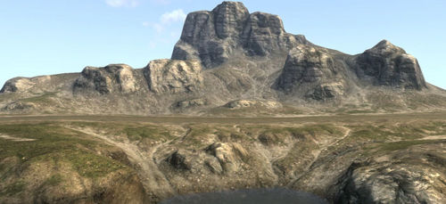
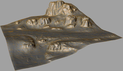
This guide will show you step by step, on how to create a detailed Megatextured Terrain.
Please ensure you are familiar with A Simple First Megatexture before attempting this tutorial.
Contents
Introduction
For this tutorial you must:
- Have a modelling package that can export as LWO, ASE or OBJ
- Have basic modelling skills
- Have basic mapping skills, as in A Simple First Terrain
This tutorial covers:
- Steps to create a detailed terrain mesh.
- How to assign the Megatexture
- How to add the terrain mesh to a map
- How to make a Megatexture
- How to compile a Megatexture
- How to add Water to a map
Programs used in this tutorial are:
- Mudbox
- World Machine
- Lightwave
- Maya (only used briefly)
Other similar programs can be used instead of these, but wont be covered in this tutorial.
This tutorial does not cover in detail:
- How to use Mudbox / ZBrush / World Machine / Blender / Lightwave / Maya / 3DSMax
If you already have a terrain mesh, and do not want to use Mudbox and World Machine, skip to Prepare Terrain for Megatexture.
Mudbox: Shape the Terrain
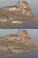
These are the basic steps for sculpting a terrain in Mudbox.
- Create a plane, and subdivide (but still keep a low tessellation).
- Change any tools you use to have the edit Direction set to Y axis.
- Create a new Layer, and sculpt the rough layout for the terrain.
- Subdivide again to the level of detail you want (or can).
- Create another layer, and sculpt more details into the terrain.
- Export to OBJ.
Convert Mesh to Heightmap
This step is needed if you want to import your current terrain mesh into World Machine.
- Firstly, rotate the terrain mesh. In Lightwave, rotate -90° around the X axis. For 3ds Max & Maya, rotate +90° around the X axis.
- Cap any holes in the mesh, and triangulate the mesh.
- Using a machine with an nVidia graphics card, run the following command in the ETQW console to get the heightmap (where <model> is the relative path of the .lwo, .obj or .ase mesh):
- RenderBumpFlat –floatHeightmap -size 2048 2048 <model>
- An .r32 (raw 32-bit) heightmap will be saved into the same folder as your model, this heightmap can be used in World Machine.
World Machine: Adding Flow
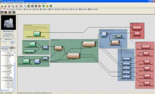
World Machine is used to add erosion flow lines to the terrain. It's also useful as the flow maps can be exported to help create masks for texture distribution later in Terrain Editor. These are the basic steps made to build the World Machine device nodes.
- Blend the heightmap made from the Mudbox mesh with Perlin Noise to help the Erosion filters.
- Use a Snow filter around the rocks (mask used), so rocks look like they are sitting in soil.
- Pass the heightmap through two Erosion nodes, which are set up differently, and combined give a natural flowing look. Both Erosion nodes are masked around the rocks, so they will keep their shape. The first Erosion node is setup as Channeled Erosion with an Inverse Filter, carving large flow lines into the terrain. The Second is a Channeled Erosion set with No Filter , adding finer detailed flow lines.
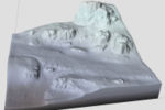
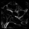
- The heightmap output of the erosion is split so the heightmap can be saved (and later used to create a mesh), and further filters created (sediment and normal map) to help make masks for texture distribution later.
- Flow and Deposition maps from the Erosion nodes are passed through Simple Transformation nodes that brighten the output saved.
- The heightmap saved above is imported and rendered at a lower (usable) resolution to the Mesh Output node creating an OBJ mesh.
This World Machine example was given using World Machine 2, which is currently in Beta. A couple of features show aren't available in World Machine v1.25. They are the Snow node (which isn't needed) and Mesh Output. An alternative to creating a mesh from a heightmap can be found here.
High to Low poly
Optimizing
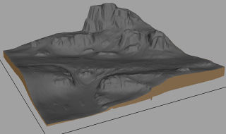
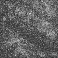
This stage will briefly explain how the high-poly mesh exported from World Machine can be optimized down to the low poly game mesh.
- Load the OBJ exported from World Machine into your preferred 3d Application.
- Rotate so it's orientated correctly.
- The outer mesh border will look like it's been dragged down (an artifact from the mesh being built from a heightmap). So remove this by selecting the mesh border polygons, and delete them.
- Triangulate the mesh and save out as .OBJ, so it can be loaded into Lightwave.
- In Lightwave, use a plug-in called qemLOSS3 (once installed, found in the Utilities tab) to reduce the polygons to a reasonable amount (ETQW used around 30,000 polygons for the 32,768 unit width terrain). If you have trouble running qemLOSS3, apply a different material other than the default.
- Fix edges that are triangulated in the wrong direction.
- Smooth subdivide the mesh, and run your mesh through qemLOSS3 again (to the same polygon count as before). This will give a smoother terrain, easier for player movement and with less harsh silhouette angles. Repeat until you're happy with the mesh smoothness.
- Again fix edges that are triangulated in the wrong direction (these show up most obviously by applying a shiny material, and making sure the mesh has a single smoothing group (all soft edges, 180 degree smoothing angle).
- If you plan on having water, cut the mesh along the waterline, so no polygons are both above or below the water. This is so the water fog has a clear line to stop at.
UV the Terrain
This process is written for Maya, other 3d packages will have to modify the process.
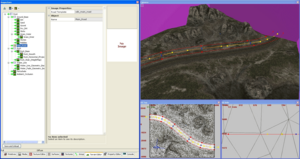
- To achieve relaxed UV borders use a mel script called worldSpaceUVLine - it can be found on Highend3D. Copy the .mel into your My Documents\maya\#.#\scripts folder and run by typing worldSpaceUVLine; in the Maya command line.
- Snap all 4 corners to the UV 0-1 square. Select all the edge uv for one side, and in the worldSpaceUVLine tool select the corresponding UV layout direction (U for horizontal, V for vertical), and press the align UV’s on selected line button. Repeat for each side.
- Make sure all holes in the mesh are capped, and run the Relax UVs tool, with the option Edge Weights set to World Space, and Pin UV Border selected. Keep repeating Relax UVs until you see no more UV movement.
Perturbate Image (Normal Map)
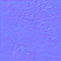
The Perturbate Image is an image that is applied to the megatexture, and corrects the low poly mesh normal to match that of the high poly.
- Load the high and low poly mesh into your preferred 3d Application.
- Use a surface-sampler (also known as baking textures, or render-to-texture, most good 3D applications will have this capability) to render the high poly normals onto the low poly model, with normals set to "tangent space".
- You probably will need to fix the normal map channels (red and green) as the 3D Application use normals maps differently to the Game. Make sure the green channel has white facing down, and red has white facing right.
Convert World Machine masks to UV space
All the masks created created in World Machine (flow, deposition etc.) won't match the new game mesh UV coordinates
- Load the high and low poly mesh into your preferred 3D application.
- Duplicate the game mesh and apply a planar UV projection.
- Apply the masks created in World Machine to the planar mapped mesh.
- Surface sample the diffuse from the planar mapped mesh, onto the game UV mesh.
Also render the mesh normals (world space) to an image. The blue channel will become useful when creating distribution masks, as it represents how vertical a polygon is.
Prepare Terrain for Megatexture
Now the mesh is nearly ready for the game, just a couple more steps.
Prepare the Mesh
- Scale the game mesh to the correct size, as after converting from a heightmap it probably isn't the right size. This tutorial mesh is a small 8,192 x 8,192 unit mesh (again the Enemy Territory : Quake Wars terrains are 32,768 x 32,768).
- Rename the material to megatextures/sdk/terrain_mesh_sdk (megatextures/<map_name>). Maya will have problems with this naming convention.
- Set the Mesh normals to be smooth.
- Save the mesh to /models/terrain/sdk/terrain_mesh_sdk.lwo (<map_name>.lwo or .obj to /models/terrain).
Setup the Material
- Create a text file called /materials/megatextures_sdk.mtr
- Add the following text to create the material:
material megatextures/sdk/terrain_mesh_sdk { useTemplate megatextures/default_ambient< "sdk/terrain_mesh_sdk" > }
- Save the file. You will need to restart the whole game and editor before any new files are loaded. If you just added the declaration to an existing .mtr file, you can just use the reloaddecls console command.
Construct the Megatexture
This section will cover the step by step creation of the Megatexture using Terrain Editor (an inspector tab in EditWorld). For Detailed explanation on feilds and setting not discussed here, check out the Terrain Editor
Set up the Map
- Load EditWorld, and create a new map.
- Bring up the Terrain Editor inspector.
- RMB in the left blank (white) area. In the pop-up menu select New | Tree...
- On the Root node set the model field to /models/terrain/sdk/terrain_mesh_sdk.lwo, and also set the ST Model to the same model. If you have holes in your mesh (holes cut for buildings), you'd need to make a separate ST Model version with no mesh holes.
- Seal the map up by Creating a Caulk Hull. Make sure the origin of the terrain mesh is inside this hull.
- For the area to be lit by the sun, create a brush inside the caulk hull, textured with 'editor/outsideportal'.
- To set the atmosphere create an Atmosphere entity and set atmospheredecl to Valley01 (or what ever atmosphere you're using).
Detail Textures
Also on the Root node is where the detail textures are assigned. In each of the layers created, you assign which of these 4 detail textures to use. Detail Textures need to be a greyscale 512x512 texture (preferably saved in base/textures/detail/).
| Detail Texture 0 | textures/detail/temperate_dirt.tga | |
| Detail Texture 1 | textures/detail/temperate_grass.tga | |
| Detail Texture 2 | textures/detail/temperate_gravel.tga | |
| Detail Texture 3 | textures/detail/temperate_rock.tga |
Image Sources
Here we'll start to create the texture layers that build up the Megatexture. The steps will progressively skip repetitive information about the layer setup.
- Ground_Base
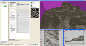
- Create a Group node, RMB and with the pop-up menu select New | Group. In the right field you can enter a name for the Group, we'll name this one Ground_Base.
- Dirt
- Now we'll create a base Image Source node. RMB over the Group node, and create an Image Source node, this should create it as a child to the Group. If you accidently created the Image node under the Root, don't worry as you can drag and release over the Group node to make it a child. Name the Layer Dirt, same way as the Group node.
- Apply a Diffuse texture by selecting Diffuse on the right hand panel of the inspector, then selecting the File Name field and press the ... button to choose a texture. For this layer we'll use textures/megagen/temperate/dirt_06_d.tga
- Repeat the same process for the Local image by selecting Local on the right, and applying the texture textures/megagen/temperate/dirt_06_local.tga
- As this is the base layer, the Distribution needs to cover the whole map. So apply a full white image the same way as above but to the Distribution.
- This layer is a dirt layer so I'll set the the Detail Texture Type to 0, to match the number for the dirt detail texture.
- Also as this layer is dirt I'll set Sur Type Properties | Type to dirt. For a full list of usable surface types, check the Surface Type section.
- The diffuse texture has the dimensions 1024 x 1024, while the map covers 8192. To keep the correct texture ratio, set Texture Properties | Scale to 8 8.
- Texture Properties | Rotation is set to 270 to keep the to match the texture lighting to that of the atmosphere.
- Sand
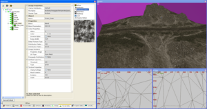
- Sand will settle along the flow lines, as it's been washed down with the weather.
- Create this layer in the same way as the Dirt layer. The Diffuse and Local can also be set up in the same way except choosing textures/megagen/temperate/dirt_07.* as the textures.
- This layer will require a unique Distribution image. The flow masks (UV corrected) created from World Machine were used to help create textures/megagen/terrain_mesh_sdk/masks/masks_sand.tga which is applied as the Distribution.
- To make the blend more fitting and unique set the Distribution Pattern to textures/megagen/temperate/dirt_06_mask_inverse.tga. This will blend the Sand into the cracks of the Dirt before the peaks (stones).
- Ramp Width is changed to 0.5 so the blend will become tighter.
- Distribution Pattern Texture Rotation and Scale Should match that of the Dirt layer, as it's using a Distribution Pattern that matches the dirt.
- Set the Detail Texture Type to 0 (dirt, as it's the best matching of the four), and the Surface Type Properties | Type to sand.
- To see how the Megatexture is progressing, render a Megatexture Preview

- Gravel
- To give the look off loose stones being scatter from the road.
- Create in the same way as above. Was created after the Road Layer being placed.
- The Distribution Pattern image for this layer will match it's own gravel diffuse, so the Rotation and Scale for the Diffuse and Distribution Pattern images should be the same.
- Set the Detail Texture Type to 2 (textures/detail/temperate_gravel.tga), and the Surface Type Properties | Type to gravel.
- Dry_Dirt
- Gives a dried up cracked earth appearance, were standing water would have once been.
- Slight transparency given so layer blends smoother over light sand and darker dirt, Alpha set to 0.75
- Ramp Width set to 0.25 making the blend even tighter (sharper).
- Sticks
- Helps the grass blend in with the dirt.
- Created after the grass, then layer moved above by dragging and releasing between the layers Grass_Outer and Dry_Dirt.
- Ramp Width set to 0.75 so the blend can be softer.
- Grass_Outer
- Texture used is of a patchy grass, good for grass on the edges of a grass clump.
- Distribution Pattern texture carefully made so the dirt parts of the diffuse blend in last.
- Texture Rotation set to 300, this is to break up the look of textures tiling in the same direction.
- The Detail Texture Type is set to 1 (textures/detail/temperate_grass.tga), and the Surface Type Properties | Type to grass.
- Grass_Inner
- Dense Grass, blended to cover the dirt of the patchy grass texture (Grass_Outer), where the mask become more solid (white).
- Uses the same Distribution mask as Grass_Outer, as the Distribution Pattern texture is made so that it is never stronger than that of the patchy grass.
- Texture Rotation and Scale needs to match that of Grass_Outer as the Distribution Pattern textures of both grass layers work together, with the same Distribution.
- Stones
- Create the Stone Distribution after the solid rock layers, as the rock will look better when it blends to the stones. To find out where rocks are distributed exactly, Preview Render the megatexture with the rocks layer tinted black, and only a white base layer. The Preview Megatexture will be saved to <span style="padding: 0 0.5ex; background: #def;" title="A file or folder named 'base/imagedump/maps/<map_name>'">base/imagedump/maps/<map_name> and flipped vertically.
- As well as being concentrated around the solid rock sections, stones should flow down the surrounding slopes.
- Make the Stones more dense around rocks.
- The Distribution Pattern texture has been created so the stones will blend in one by one.
- Pebbles
- Pebbles in Mud works well around the waterline.
- The Distribution mask is made slightly darker where the sand Distribution is. This will give good variation, as the Pebbles will blend in first (due to Distribution Pattern), making them appear to be on sand instead of mud.
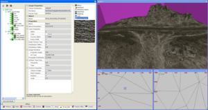
- Rock
- A new Group is created under the Root node to keep the rock elements neatly together.
- Rock_Base
- Rock should usually be created (distributed) near the start of making a Megatexture, as rock usually effects where all other elements will be distributed.
- Texture Rotation for both Diffuse and Distribution Pattern is set to 0.45, this is so the rock diffuse is rotated to match the direction of the rock in the map. If you have rock in all directions you could make separate rock masks for the different rotations.
- A Heightmap image is assigned, textures/megagen/temperate/rock_01_h.tga. This will help the Rock_Stain_(HeightMap) blend into the cracks.
- Set the Propagate Distribution to true, by ticking the box. This will mask any child layers with this layers distribution.
- The Detail Texture Type is set to 3 (textures/detail/temperate_rock.tga), and the Surface Type Properties | Type to stone.
- Rock_Smooth
- By distributing smooth rock on raised and large flat areas, while not in cracks and around rock edges, will help to give it shape.
- This layer can be set up in the same way as Rock_Base (including having a heightmap image), except you don't need to Propagate Distribution.
- Use the same Distribution Pattern used in Rock_Base so the smooth rock will form on the ridges first.
- Rock_Horizontal
- This layer will use a different technique to create horizontal crack lines in the rock.
- Most of the settings can be set up in the same way as the previous rock layers.
- Use the same Distribution Pattern used in Rock_Base (including the same scale and rotation).
- Set the Projector Pattern image to the horizontal rock distribution pattern (textures/megagen/temperate/rock_04_mask.tga).
- Set the last value of the Blend Parameters giving 0 0 0 0.75, this controls the sharpness off the Projector Pattern blend.
- The Distribution mask should only include steep polygons that face the angle of projection (this will prevent texture stretching).
- Set Image Renderer | UV Type to Parallel Side. This will force the layer to render has a side projection. For this to work correctly, the terrain mesh needs to be centered around the grid origin.
- Set Image Renderer | Projection Angle to 135, so the projection is in the direction of the vertical rock face (this will rotate the projection around the Z axis).
- Texture Properties | Scale to 6 2, as this is a side projection, the number of tiles should match the side profile of the mesh.
- Rock_Stain(Heightmap)
- This layer will create darker staining on the rock, by the use of a heightmap blend.
- The way this blend method works is it renders all the heightmaps from each of the layers first, and then blends the diffuse & local images into the lower (darker) parts of the heightmap.
- Assign a black texture (textures/megagen/black.tga) to the Heightmap image, this will help the staining occur stronger based on the Distribution mask.
- Set the first 2 values of the Blend Parameters giving 0.33 0.25 0 0 . The first value (0.33) controls the height at which the blend takes place, while the second (0.25) controls the sharpness of the falloff in the blend.
- Set the Color of the layer to black, either by texture or color tinting.
- No Local map required
- Alpha set to 0.5 so the rock texture underneath shows through.
- Detail Texture Type set to -1 , this will disable distributing detail textures for this layer.
- Leave the Surface Type Properties | Type field blank.
- Water_Line
- A new Group is created under the Root node to keep the water line elements neatly together.
- Water_Line_(Geometry_Based)
- This layer will give a look of wet ground.
- Set the Blend mode to Multiply (d*s), this will darken (multiply) over the textures underneath.
- Assign the Diffuse to textures/megagen/white.tga, and Color tint to Hue 0, Saturation 0, Brightness 180
- For the Distribution, change Source Type to geometryBased. Enable the Altitude Upper, set the Value to 800 (32 units just above the water line), and Fuzziness to 0.075 (the falloff). Resolution can be set to 1024 (generated texture size of the mask).
- Again Detail Texture Type set to -1
- Surface Type Properties | Type set to water, so allow splashes to form on the shoreline.
- Water_Fade_(Geometry_Based)
- This will help give the water depth (and reduce megatexture size ;)
- Setup in the same way as Water_Line_(Geometry_Based) above, except:
- Set the Blend mode to Blend, this will cover over the textures underneath (looking similar to fog).
- Color tint set to Hue 60, Saturation 115, Brightness 22
- With Source Type set to geometryBased, change the Altitude Upper | Value to 768 (water height) and Fuzziness to 1 (larger falloff).
- Perturbate
- Create under the Root node. Will bring back the normals to that of the high-res mesh, improving the baked lighting.
- Set the Blend mode to Perturbate Normals, this will add the normals to those already generated by the other layers.
- Assign no Diffuse texture.
- Assign a white texture to the Distribution (as to cover the whole megatexture).
- Set the Local texture to textures/megagen/terrain_mesh_sdk/local.tga (the mesh's normal map).
- Detail Texture Type set to -1
- Leave the Surface Type Properties | Type field blank.
- Ambient_Occlusion
- Also created under the Root node. Rendered in Maya to emulate light being occluded in crevices.
- Set the Blend mode to Multiply (d*(s*1.6). in this blend mode diffuse image colors darker than 160 will darken the previous layers, while colors brighter than 160 will lighten.
- Assign textures/megagen/terrain_mesh_sdk/ambient_occlusion.tga as the Diffuse. The image is balanced so that areas of no change are around 160 in color brightness.
- Assign a white texture to the Distribution (as to cover the whole megatexture).
- Detail Texture Type set to -1
- Leave the Surface Type Properties | Type field blank.
Road Tool
Here we'll create a paved road using the Road Tool.
- First we'll create a Road Template (.rtl), to assign what textures and surface type to assign to the road.
- Create a blank text file called /megagen/roadtemplates/terrain_mesh_sdk.rtl and add the needed information:
roadTemplate sdk_main_road {
    {
        diffuse image sdTextureTGA_Properties {
            name "textures/megagen/temperate/road_01_d.tga"
        }
        local image sdTextureTGA_Properties {
            name "textures/megagen/temperate/road_01_local.tga"
        }
        distribution image sdTextureTGA_Properties {
            name "textures/megagen/temperate/road_01_mask.tga"
        }
        offset ( -1 1 )
        surfaceType "pavement"
        detailtexture "textures/detail/temperate_gravel.tga"
        }
}
Here we've given the road material a name sdk_main_road, and set the Diffuse, Local, and Mask textures. Also setting the Surface Type to pavemant, and Detail Texture to textures/detail/temperate_gravel.tga (which also must be assigned in the Root node).
- Main_Road
- Create the Road node, RMB over the Root node, a pop-up menu will appear and select New | Road.
- Set Road Template to sdk_main_road, this points the road tool to the correct road template.
- Start placing the road along the map:
- Select the node
- Click on the XY Top window
- Enter vertex editing mode (v)
- Hold CtrlShift and lmb in the XY Top window to start placing the points that make up the road curve.
- Now to fix the width and direction of the road.
- You need to be in vertex editing mode if not already (toggled with v).
- Moving Road Points LMB-drag the blue points.
- Change Points Direction LMB-drag the yellow points.
- Change Width of Road LMB-drag out the red points. Alternatively you can widen the whole road when outside the vertex editing mode by selecting the Road node, then LMB-drag beside the road.
- Adding new Points hold CtrlShift and lmb the area where you want create the new point.
- Deleting Points LMB and hold the blue point you want to delete and press Backspace.
- Press Esc to exit vertex editing mode.
- The Road Tool must never cross a mesh border, so make sure you bump in your road by at least one unit. If it does cross a border the Road Tool will render with an artifact stretching to the mesh corner.
- Finally move the layer into it's correct place for rendering. Drag and release the node between the Ground_Base and Rock group node.
Projector
Using the projector node, localized texture detail can be projected onto the megatexture.
- Projectors
Created a groups to keep things nice an neat.
- Cracked_Road
- To give the look of cracked tar where the crater nears the road.
- Create the Road Node, RMB over the Projectors Group node, a pop-up menu will appear and select New | Projector.
- Setup the Projector the same way you would a standard Image Source node, except you only need a Distribution mask (and not a Distributed Pattern), as the texture shouldn't be projected larger than the source textures.
- To place the projector move/scale/rotate as you would a normal brush (including vertex editing). The projector should be positioned above the terrain mesh.
- Crater
- Places the crater scorch marks.
- Setup the same way as Cracked_Road.
See Also
- A Simple First Megatexture - start here for a basic MegaTexture tutorial
- Generate a MegaTexture - steps for generating a MegaTexture from the SDK launcher.
